Full image coverage of a borehole wall – the acoustic scanner probe.
The acoustic scanner, also known as the acoustic televiewer, uses high frequency sound wave echoes together with magnetometers and accelerometers to provide an orientated travel time and amplitude image of the borehole wall.
Principal features
- Identifies and orientates (measures the dip angle and dip direction) of fractures, joints or other rock breaks.
- Measures the frequency of fractures/joints with depth
- High resolution caliper tool
Applications
- Geotechnical site investigations where slope stability, rock support are key requirements.
- Tunnelling
- Structural geology
The technique.
Two images are produced which are presented as “unwrapped” images (imagine pealing a layer of skin from the borehole wall and laying it on a flat surface):

- A Two Way Travel Time (TWTT) image which represents the time taken for the acoustic pulse to travel from the acoustic source in the probe through the borehole fluid to the borehole wall and back through the borehole fluid to the probe. It represents a detailed, high resolution caliper curve.
- An amplitude (C AMP) image which represents the “strength” of the recorded acoustic pulse in the probe after reflection back from the borehole wall. The image is a false coloured image of acoustic impedance contrast. Essentially bright colours represent high amplitude signal, hard rock and dark colours represent low amplitude signal, soft rock or borehole fluid.
How the image data is sampled?

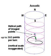
The 360 degree image coverage of the borehole wall is obtained through a rotating, angled mirror below an acoustic transducer which through clever timing synchronisation acts as a transmitter and receiver of the ultrasonic echoes. Another feature of the probe which increases the vertical resolution of the image data is focusing of the acoustic echoes through a curved and angled mirror.
Orientation of the image data
Orientation of the image (by orientation we mean a Magnetic North reference or a reference to the high side of the borehole) is achieved using a three axis magnetometer and a three axis accelerometer inside the probe.
Borehole and Probe Requirements
The following conditions in the borehole are required![]()
- A fluid in the borehole:
– An ultrasonic signal cannot be sustained in air.
– The fluid can be water (of any salinity) or drilling mud.
– Heavy drilling muds can affect the signal quality.
- The probe needs to be centrallised:
– Achieved by using two spring centrallisers located towards the top and bottom of the probe.
– Allows the acoustic echoes to be reflected perpendicular to the borehole wall.
- Borehole diameter range:
– Minimum diameter of 50mm.
– Maximum diameter up to 400mm depending upon borehole fluid properties.
Data acquisition settings
- The number of data samples per revolution of the acoustic mirror varies between acquisition systems.
- Variations include every 90 (72), 180 (144), 270 and 360 (288) samples per revolution.
- Lower rotational sample rates are common for smaller diameter boreholes (180 (144) common for 96mm diameter)
- Larger diameter boreholes demand greater rotational sample rates and a slower revolution of the acoustic mirror.
- Most acoustic scanner logging systems require a minimum and maximum setting for the expected acoustic echo. This is typically borehole diameter and fluid dependent. Some logging systems have an “automatic mode” where digital capture settings are based upon the received echo features.
- Acoustic scanner data files are large.
- Data transfer speeds of the logging system control the logging speed during acquisition. A logging speed of around 2 m/min is not uncommon.
- Newer logging systems allow a higher data transfer speed, hence a greater logging speed for the same image resolution.
Data Processing
Once the image data has been acquired, the power of the borehole imaging technique is that structures which cut across the borehole can be identified and have the dip angle and dip direction individually measured.
Remember the “unwrapped image”? In this format, any dipping structure forms a sine curve from which the structure’s dip angle and dip direction (initially with respect to the dip and dip direction of the borehole) can be calculated.
Whilst the technique could be likened to structure orientation from drill core, the acoustic scanner data is more diverse, more accurate and much more time effective.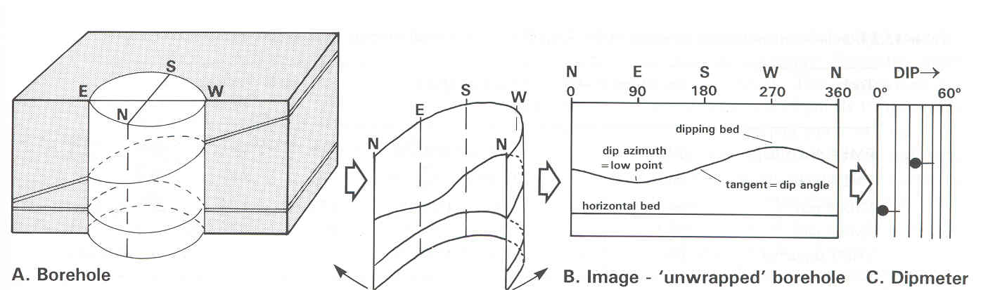
The final product
Once the image data has been acquired, the power of the borehole imaging technique is that structures which cut across the borehole can be identified and have the dip angle and dip direction individually measured.
- Structures are orientated and classified, then ready for presentation as a list and/or in a stereographic projection.
- Combined with other geophysical or geological data from the borehole
- 3D borehole image representation