There are several types of flowmeter probes available to identify, measure and quantify the flow of groundwater in a borehole. Such data will provide important insights into the local hydrogeology which includes:
• Source of groundwater flow in a borehole.
• “Thief zones” where groundwater is being lost from a borehole.
• Measure and quantify vertical flow rates in a borehole.
These measurements can be made immediately after original drilling process, during pump testing and/ or in the completed borehole.
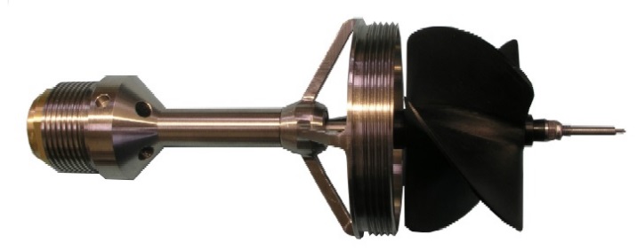
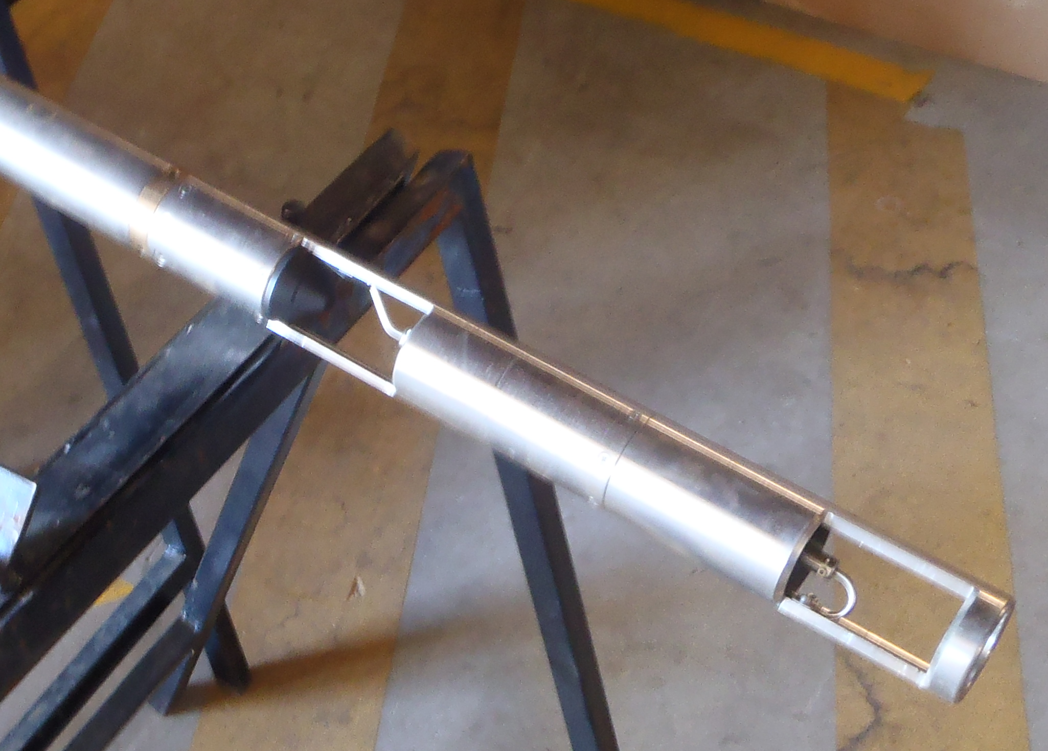
Impeller flowmeter
The impeller flowmeter has a small impeller blade commonly mounted in a cage for protection. The protective cage also acts to channel flow through to the impeller blade. Modern probes have a range of cage and impeller sizes to suit most borehole diameters. Movement of the impeller in either direction is recorded to measure vertical flow in a borehole.
Measurements can be made with the probe stationary. These would be undertaken under natural artesian borehole conditions or under induced pumping conditions. Another traditional form of impeller flowmeter logging is to run the probe uphole and downhole at a fixed logging speed.
Despite the impeller blade sitting on jewelled bearings, there is a necessary threshold flow rate required for the impeller blade to rotate and make a measurement.
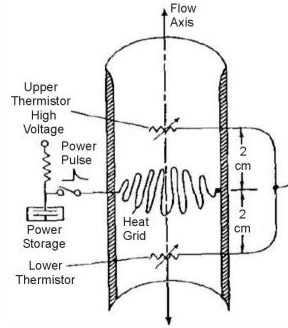
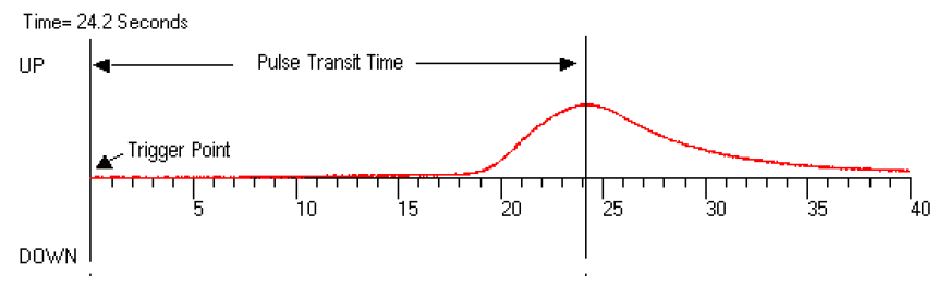
Heatpulse flowmeter
The heatpulse flowmeter is available to measure very low flow rates. Such flow rates cannot be measured by the impeller flowmeter. Measurements are made with the probe stationary.
The heatpulse flowmeter employs an electronically generated pulse of heat to measure flow direction and flow rate through sensitive thermistor based detectors set above and below the heat source.
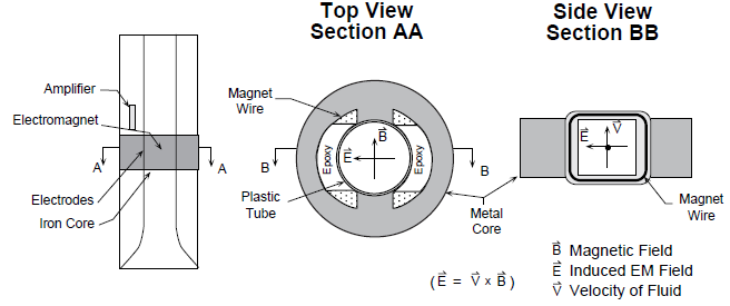
Electromagnetic (EM) flowmeter
As with the heatpulse flowmeter the electromagnetic (EM) flowmeter is available to measure very low flow rates. Such flow rates cannot be measured by the impeller flowmeter. Measurements are made with the probe stationary.
The electromagnetic (EM) flowmeter employs an electromagnet and an electrode above and below. Where the electromagnet generates a magnetic field and the electrodes measure any induce voltage associated with groundwater flow in the borehole.
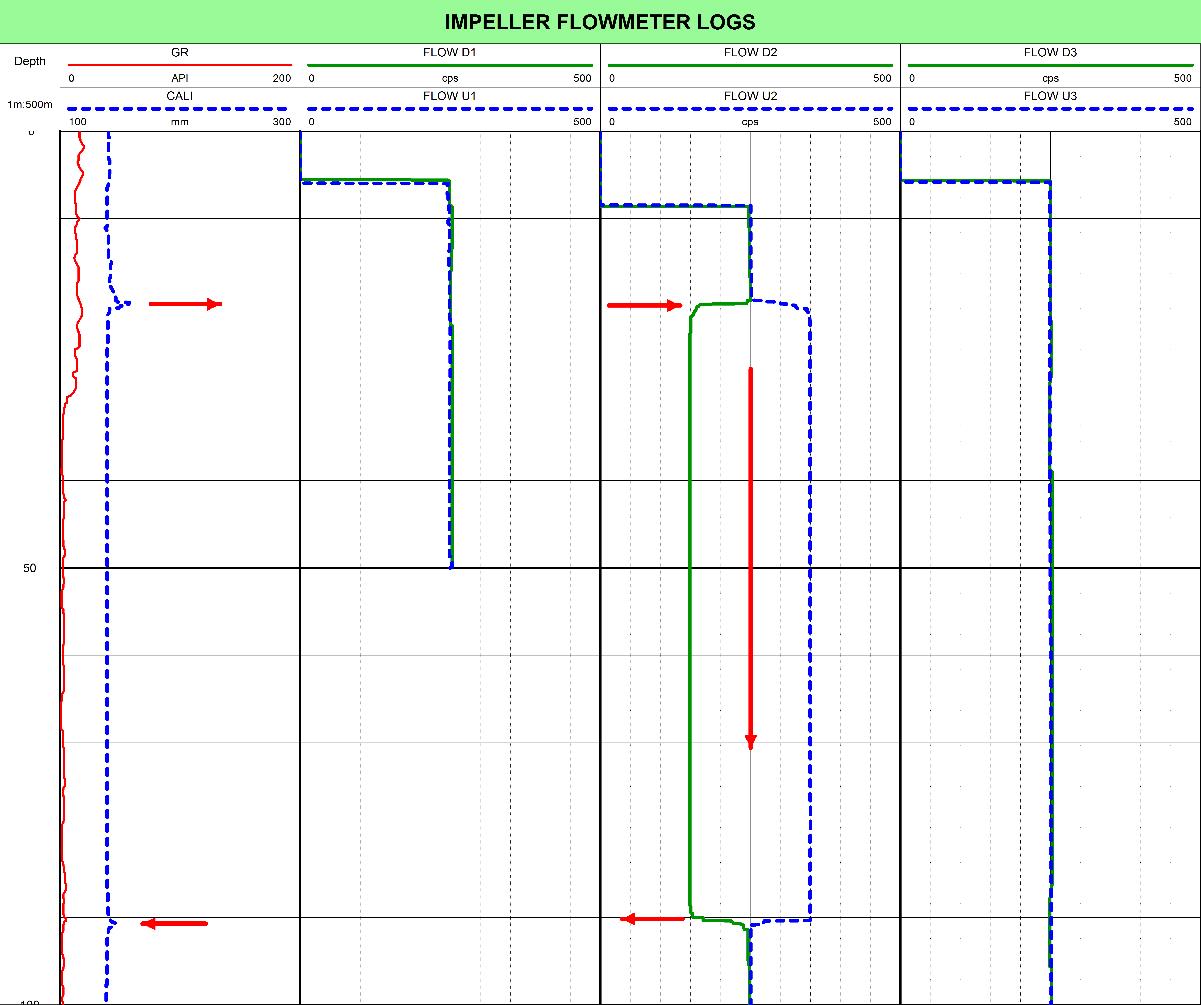
Impeller Flowmeter Example
During drilling of an exploratory borehole in a wadi system in the Middle East, the local “falaj” water supply dried up – suffice to say the local farmers were not happy. The aquifer supplying the “falaj” system was in near surface alluvial gravels which overlaid limestone bedrock.
All was fine during drilling until a depth around 120m when the water in the alluvial gravels drained rapidly into the limestone bedrock.
Impeller flowmeter logging indicated a rapid downhole flow of the water from the alluvial gravels to the fractured limestone (downhole impeller rotation was significantly less than uphole impeller rotation). This separation finished below 120m – the uphole and downhole curves overlaid). A caliper log identified a fracture in the limestone bedrock at 120m. This fracture was acting as a “thief zone” (similar to pulling the plug out of a bath) draining all the water from the alluvial gravels into the limestone bedrock.
Drilling continued to 150m, after which a steel casing string was inserted to 130m and the annulus cemented.
The flow for the alluvial gravels into the limestone bedrock stopped and the “falaj” water supply was re-instated.