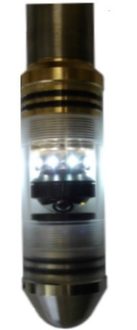
Full image coverage of a borehole wall in true colour – the optical scanner probe
The optical scanner uses a high resolution digital camera together with magnetometers and accelerometers to provide an orientated true colour image of the borehole wall.
Principal features
- Identifies and orientates (measures the dip angle and dip direction) of fractures, joints or other rock breaks.
- Measure the frequency of fractures/joints with depth
Applications
- Geotechnical site investigations where slope stability, rock support are key requirements.
- Tunnelling
- Structural geology
Technique

A single image is produced through a digital video camera which can capture image data at a rate of 60 frames per second. Full pixel by pixel colour calibration occurs to ensure a perfect colour balance.
The camera is focused through a prism allowing 360° slices of the full borehole wall to be recorded.
A ring of LED lights provides light for the digital camera
Orientation of the image data
Orientation of the image (by orientation we mean a Magnetic North reference or a reference to the high side of the borehole) is achieved using a three axis magnetometer and a three axis accelerometer inside the probe.
Borehole and Probe Requirements
The following conditions in the borehole are required:
- The probe needs to “see” the side of the borehole wall
- Air filled boreholes.
- Clear fluid filled boreholes.
- The probe needs to be centrallised – achieved by using two spring centrallisers located towards the top and bottom of the probe.
- Borehole diameter range:
– Minimum diameter of 50mm.
– Maximum diameter up to 400mm depending viewing conditions.
Data acquisition settings
- Pixel resolution settings range from 720 dpi up to 1440 dpi.
- Optical image resolution below 1mm is possible. The greater the image resolution, the lower the logging speed.
- User control over light, frame rate and exposure settings covers most borehole conditions.
- Optical scanner data files can be very large.
- Data transfer speeds of the logging system control the logging speed during acquisition. A logging speed of around 4 m/min is not uncommon.
- Newer logging systems allow a higher data transfer speed, hence a greater logging speed for the same image resolution.
Data Processing
Once the image data has been acquired, the power of the borehole imaging technique is that structures which cut across the borehole can be identified and have the dip angle and dip direction individually measured.
Remember the “unwrapped image”? In this format, any dipping structure forms a sine curve from which the structure’s dip angle and dip direction (initially with respect to the dip and dip direction of the borehole) can be calculated.
Whilst the technique could be likened to structure orientation from drill core, the acoustic scanner data is more diverse, more accurate and much more time effective.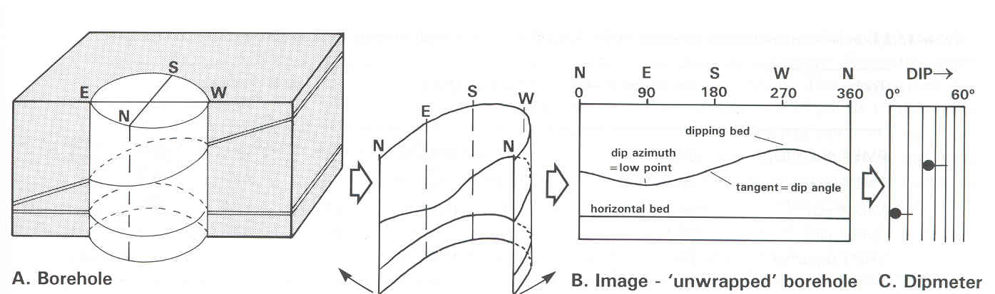
The final product
Once the image data has been acquired, the power of the borehole imaging technique is that structures which cut across the borehole can be identified and have the dip angle and dip direction individually measured.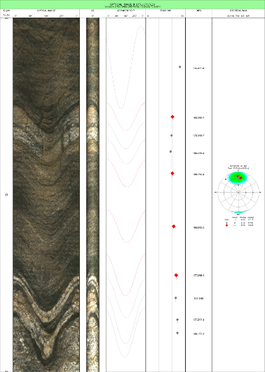
- Structures are orientated and classified, then ready for presentation as a list and/or in a stereographic projection.
- Combined with other geophysical or geological data from the borehole
- 3D borehole image representation